To Create a Wiring Diagram Symbol (Four Pole Relay)
Wiring diagrams
are graphical representations of connection information. The wiring diagram
includes a wiring diagram symbol for each device in the schematic with
connection data appearing next to it. Alternatively, wiring diagrams can use
tables to display connection data, in which case special wiring diagram symbols
are not required. A number of wiring diagram symbols are provided with the
software. These have symbol names that begin with W- characters; however, this
naming format is not required.
General Points About Wiring Diagram Symbols
The following is an example of how to create a wiring diagram symbol for a four pole relay.
- Select to display the Symbol Creation Wizard.
- In this example, you will create a symbol from scratch. Select New Symbol (from Scratch), then press Next.
- In Step 2 of the Symbol Creation Wizard, enable the Wiring Diagram option within the Symbol Type group box to define the symbol type, then press Next.
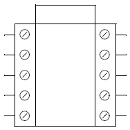
- In Step 3 of the Symbol Creation Wizard, you will import connection points from a similar symbol or family to save time. First, however, you will draw the graphics of the symbol using graphical drawing functions (not wires). Make the symbol approximately 4 inches (100 mm) tall.
- Once the graphics are drawn, enable the Import Connection Points From a Family option, then press Select Family to display the Device Family dialog.
- Select the family 22, which consists of a relay with 2 normally open and 2 normally closed contacts, then press OK.
- Press Next in the Symbol Creation Wizard.
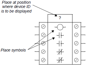
- In Step 4 of the Symbol Creation Wizard, you can enter information in the Tag Mnemonic field to indicate a default device tag (this is not required). The ID will be taken from the schematic symbol the wiring diagram symbol is representing. Type a question mark ( ?) as the default value in the Tag Mnemonic field. If desired, you can make text settings for the device ID in the Default Text Style field.
- Press Place, then click on the desired position for the device ID in the drawing.
- Use the Insert Symbol button in Step 4 of the Symbol Creation Wizard to select and insert the coil (CR) and contact (CRNO, CRNC) symbols. This will visually mark the position of the parent and child symbol data.
- Delete the function text for the coil symbol, then press Next to continue.
- In Step 5 of the Symbol Creation Wizard, you will place connection points on the symbol to set where the connection information will be displayed. The imported connection points from the family selected in Step 3 are displayed. The Visible Text entry (?) is a default value for the connection point text. The software will replace the visible text with the connection expression defined in the Wiring Diagram Settings dialog. The Hidden Text entries are the connection point designations that were defined in the family. If you had not imported connection points from a family or symbol, you could make an entry in the Number of Connection Points field to create the connection points. Because you imported connection points for this symbol from an existing family, there are also entries in the Role column for each connection point indicating the parent or child that the connection applies to.
- Make the desired text settings before placing the connection points. Use Middle Right text alignment for connections on the left side of the symbol. Use Middle Left text alignment for connections on the right side of the symbol.
- Select a connection point, then press Place. You will be prompted on the command line to select the connection point position and then the connection point text position. The placement of the connection points is not critical, but they should be on the same side of the symbol as the corresponding connection point text. After a connection point is placed, it is marked with an X in the Symbol Creation Wizard in the left-most column.
- Press Next to continue.
- In Step 6 of the Symbol Creation Wizard, you can specify symbol attributes. You will not be using attributes in this example. Press Next to continue.
- In Step 7 of the Symbol Creation Wizard, select the insertion point for the symbol by pressing Pick Point within the Insertion Point group-box, then click on the upper left corner of the symbol. A red arrow marks the selected point.
- Press Next to continue.
- In Step 8 of the Symbol Creation Wizard, you will name and save the symbol. Type W-EXWDG in the Symbol Name field, then enter a description of the symbol in the Description field. Use the Save in field to select the catalog in which to save the symbol.
- Press Finish.